Tuesday, October 20, 2009

Lab 4 - Our process, in detail

Method
In the previous lab, we were using a Hall-effect sensor to measure the position of the pendulum. The sensor produced voltage in the range of 2.0V to 3.0 V, which is read by the Arduino's analog reading as a value between 495 and 540. With this range, the position only has 45 data points and this resolution is not sufficient to reproduce a good virtual spring and damping. When we use the sensor readings to determine the speed of the pendulum, it often takes into account the random noise from the Hall-effect sensor and since the resolution was poor, the PWM output tended to be large. This resulted in a lot of stability problem in our control.

In this lab, we used OP Amp to amplify the voltage range so that the output voltage came in the voltage range of 0V to 5.0V, which enabled us to use the full extent of the Arduino's analog input range. Below is the circuit diagram of the OP Amp we used in this lab.

We set the positive terminal to be 2.5V so that the neutral position of the output voltage from the OP Amp to be 2.5V. We choose this value to match the middle output of the Hall-effect sensor. The resistors in the negative terminal are used to amplify the ±0.5V voltage range from the Hall-effect into ±2.5V so that the voltage output range from the OP Amp has a range of 2.5V ±2.5V or 0V to 5V. Since this is an inverting OP Amp, the gain is reversed so that 2.5V±0.5V range translated into 2.5V±(-2.5V) range for the output from the OP Amp.

Theoretically, we should get this range of 0V to 5.0V, but the middle point of the Hall-effect sensor turned out to be not exactly on 2.5V, so the actual output voltage range from the OP Amp came out to be between 0V and 4.0V. This is still a huge increase in voltage range, and the analog reading from the Arduino read values between 0 and 827. The new range has more than 800 data points, which is approximately 20 times as large as the original.

With the new resolution, we can try the previous lab's code to test the virtual spring and damping and see if there is any improvement in the controls.


With the new resolution from the OP Amp, we edited the previous lab's code to adjust with the new analog reading values. We decided to try the proportional control first. With the new resolution, the movement of the pendulum looked more fluid compared to the old resolution and the motion is more "spring-like". However, there are still some noises inside the reading of roughly ±30 data points, which is large because it is also got amplified by the OP Amp. When we moved into the derivative control, there was no significant improvement compared to the previous lab's. Large noises still present and instability still occurred.

You can see the proportional and derivative control at work in the video below.


Once we accomplished this, we moved to programming the Arduino to send amplified analog data from the hall effect sensor to the PD interface. We downloaded Arduino2PD patches available on programmer websites, and altered them to meet our needs, as there were no functions dedicated to actually playing the notes in the original patches.

Results
PD programming: We ended up with the program below (Note the change in port number and speed ("comport 19 38400") and the addition of five function blocks to play a note).

The first five analog in number boxes do not apply here. They would only apply if we were using multiple sensors with analog outputs. The number that we want to pay attention to is the analog in 5 number, which is the exact number that the hall effect sensor would have returned even if placed in circuit with solely the Arduino.

Discussion
Virtual environment testing: OP amp does help by increasing the resolution of the output, but does not help with reducing the noise, which was the major problem for the derivative control.

PD programming: We subtracted 500 and multiplied the result by 1.5 so that we could (a) only play notes if the armature was displaced from equilibrium and (b) get the largest range possible. If we multiplied by more than 1.5, the range would be the same but within a smaller domain. If we multiplied by less than 1.5, on the other hand, the range would not reach the highest note possible, even when armature was fully displaced. The value of 1.5 gave us the optimal performance for our set-up.

After that was completed, it was easy for us to integrate the virtual spring with tuned values from the first part of this lab. As previously mentioned in the "Accomplishments" section of the last blog post, we ended up with an instrument that played higher notes and gave higher feedback forces as the armature's displacement from center increased.

Lab 4 - Working with MIDI

The Team:
Lisa Perez
Amit Ranjan
Andrew Rohr
Eric Sihite

Our Goals for This Lab:
During the first part of this lab, we aimed to minimize quantization error by switching out our hall effect sensor from the last lab with a more sensitive hall effect sensor and maximizing the output range by the sensor by putting it in circuit with on op amp. After minimizing error, we aimed to obtain a velocity reading by differentiating the position signal with another op amp. We planned to integrate the improved settings with our virtual environments from the last lab.

The second part of lab entailed integrating a haptic environment of our motor with a MIDI interface to create a haptic instrument. For this, we aimed to understand how to send information from the Arduino to PD, our software synthesis interface, and what to program in PD to be able to get a noise and force feedback just from manipulating the motor armature.

What We Accomplished:
We were excited to use the new hall effect sensors to obtain better settings. However, shortly after soldering the terminals, one of the terminals broke, and we were not able to solder it back on. Instead, we obtained one of the older hall effect sensors and completely our work with that. We were able to get a larger output range from the op amp, with serial ouput ranging from 0 to 815 (in contrast to the approx. 500-600 range).

Even though the hall effect sensor was the same model that we had used in the last lab, we had to tweak the programming slightly to account for a difference in behavior. Once we did this, however, we were able to resimulate our virtual environments.

After we did this, we did a search on how to integrate the Arduino with PD, an interface that allows software synthesis. We learned that we could download preexisting patches for both the Arduino and PD, and altered these patches for our needs, such that the information from the hall effect sensor would transfer correctly from the Arduino to the PD interface, and consequently to the speakers.

After a few hours of looking at programming in Arduino and PD, we were able to get tones from the speakers by moving the armature back and forth. We tweaked the numbers to make it so that the armature only played if displaced from center, with higher notes being further away from center. We included a virtual spring so that the users would feel more force further away from center (and thus with a higher note).

Wednesday, October 14, 2009

Lab 3 - Virtual Environment Code (Virtual Spring-Mass)

////////////////////////////////////////////////////////////////////////
// Declare Pin Assignments
////////////////////////////////////////////////////////////////////////

const int currentSensorPin = 1;
const int positionSensorPin = 7;
const int dirMotorPin = 22;
const int pwmMotorPin = 9;
const int ledPin = 13;
const int speakerPin = 10;

////////////////////////////////////////////////////////////////////////
// Declare Variables
////////////////////////////////////////////////////////////////////////

int sensorValue = 0; // the sensor value
int sensorMin = 1023; // minimum sensor value [Position Sensor]
int sensorMax = 0; // maximum sensor value [Position Sensor]

int t_step = 5; // Delay Between Control Loops (microseconds)
int freq = 2000; // PWM Frequency (Hz)

double thetaMin = -18.0; // Minimum Position Angle
double thetaMax = 18.0; // Maximum Position Angle

int position_sign;
double pwmMin = 0.00; // Minimum Duty Cycle
double pwmMax = 1.00; // Maximum Duty Cycle
double A;
double B;

double K_m = 0.0153261; // Motor Torque Constant
double pi = 3.1415;
double delay_ = 0.001; //delay in seconds

////////////////////////////////////////////////////////////////////////
// VIRTUAL MASS-SPRING SYSTEM
////////////////////////////////////////////////////////////////////////

double xBlock0 = 0.;//0.05;
double xBlock = 0.05;
double vBlock = 0.;
double aBlock = 0.;
double mBlock = 10.;
double rLever = 0.02;
double kSpring = 100.;
double dt = 0.05;

////////////////////////////////////////////////////////////////////////
// Setup Function
////////////////////////////////////////////////////////////////////////

void setup() {

// Set Input Pins

pinMode(currentSensorPin, INPUT);
pinMode(positionSensorPin, INPUT);

// Set Output Pins

pinMode(dirMotorPin, OUTPUT);
pinMode(pwmMotorPin, OUTPUT);
pinMode(ledPin, OUTPUT);
pinMode(speakerPin, OUTPUT);

// Signal Beginning of Calibration
digitalWrite(ledPin, HIGH);

// Calibrate during First 10 Seconds
while (millis() < sensorvalue =" analogRead(positionSensorPin);"> sensorMax) {sensorMax = sensorValue;}

// record the minimum sensor value
if (sensorValue < sensorMin) {sensorMin = sensorValue;}

}

// Signal End of Calibration
digitalWrite(ledPin, LOW);

// Initialize Serial Communication Connection
Serial.begin(9600);

}

////////////////////////////////////////////////////////////////////////
// Loop Function
////////////////////////////////////////////////////////////////////////

void loop() {

double theta;
double dutyCycle = pwmMin;
double current;
double currentDesired;
double torqueDesired;

// Read Position Sensor
sensorValue = analogRead(positionSensorPin);

// Find Angle Using Sensor Value
A = (thetaMax-thetaMin)/(sensorMax-sensorMin);
B = (-0.5*(thetaMax-thetaMin))-(sensorMin*A);

theta = (A*double(sensorValue))+B;

// Print Processed Value to Serial Terminal
// Serial.print(" Theta: ");
// Serial.println(theta);

double force;

// Calculate Desired Torque
force = -1*kSpring*(xBlock - rLever*sin(theta*pi/180.));
aBlock = force/mBlock;

vBlock += aBlock*delay_;
xBlock += 0.5*aBlock*(delay_*delay_)+vBlock*delay_;

dutyCycle = force*rLever;

if (dutyCycle < 0) {position_sign = 0;}
else {position_sign = 1;}

// Use Limits on Duty Cycle
dutyCycle = constrain(abs(dutyCycle), pwmMin, pwmMax);

// Print dutyCycle to Serial Terminal
//Serial.println(dutyCycle);

// Set H-Bridge Direction
if (position_sign == 0) { digitalWrite(dirMotorPin, LOW); }
else { digitalWrite(dirMotorPin, HIGH); }

// Apply H-Bridge PWM Signal
dutyCycle = dutyCycle*255;
analogWrite(pwmMotorPin,int(dutyCycle));

delay(int(delay_*1000.));
}

Lab 3 - Virtual Environment Code (Virtual Damper)

////////////////////////////////////////////////////////////////////////
// Declare Pin Assignments
////////////////////////////////////////////////////////////////////////

const int currentSensorPin = 1;
const int positionSensorPin = 7;
const int dirMotorPin = 22;
const int pwmMotorPin = 9;
const int ledPin = 13;

////////////////////////////////////////////////////////////////////////
// Declare Variables
////////////////////////////////////////////////////////////////////////

int sensorValue = 0; // the sensor value
int sensorMin = 1023; // minimum sensor value [Position Sensor]
int sensorMax = 0; // maximum sensor value [Position Sensor]

double thetaMin = -18.0; // Minimum Position Angle
double thetaMax = 18.0; // Maximum Position Angle

int position_sign;
double pwmMin = 0.00; // Minimum Duty Cycle
double pwmMax = 1.00; // Maximum Duty Cycle
double A;
double B;

double K_m = 0.0153261; // Motor Torque Constant
double b = 0.0001;

double theta;
double dutyCycle;
double thetaOld = 0;

////////////////////////////////////////////////////////////////////////
// Setup Function
////////////////////////////////////////////////////////////////////////

void setup() {

// Set Input Pins

pinMode(currentSensorPin, INPUT);
pinMode(positionSensorPin, INPUT);

// Set Output Pins

pinMode(dirMotorPin, OUTPUT);
pinMode(pwmMotorPin, OUTPUT);
pinMode(ledPin, OUTPUT);

// Signal Beginning of Calibration
digitalWrite(ledPin, HIGH);

// Calibrate during First 10 Seconds
while (millis() < sensorvalue =" analogRead(positionSensorPin);"> sensorMax) {sensorMax = sensorValue;}

// record the minimum sensor value
if (sensorValue < sensorMin) {sensorMin = sensorValue;}

}

// Signal End of Calibration
digitalWrite(ledPin, LOW);

// Initialize Serial Communication Connection
Serial.begin(9600);

}

////////////////////////////////////////////////////////////////////////
// Loop Function
////////////////////////////////////////////////////////////////////////

void loop() {

// Read Position Sensor
sensorValue = analogRead(positionSensorPin);

// Find Angle Using Sensor Value
A = (thetaMax-thetaMin)/(sensorMax-sensorMin);
B = (-0.5*(thetaMax-thetaMin))-(sensorMin*A);

theta = (A*double(sensorValue))+B;

// Print Processed Value to Serial Terminal
// Serial.print(" Theta: ");
// Serial.println(theta);

if ((theta-thetaOld) < 0) {position_sign = 1;}
else {position_sign = 0;}

// Calculate Duty Cycle
dutyCycle = b*abs(theta-thetaOld)/(0.05);

thetaOld = theta;

// Use Limits on Duty Cycle
dutyCycle = constrain(dutyCycle, pwmMin, pwmMax);

// Print dutyCycle to Serial Terminal
// Serial.println(dutyCycle);

// Set H-Bridge Direction
if (position_sign == 1) { digitalWrite(dirMotorPin, LOW); }
else { digitalWrite(dirMotorPin, HIGH); }

// Apply H-Bridge PWM Signal
dutyCycle = dutyCycle*254;
analogWrite(pwmMotorPin,int(dutyCycle));

delay(50);

}

Lab 3 - Virtual Environment Code (Virtual Wall)

////////////////////////////////////////////////////////////////////////
// Declare Pin Assignments
////////////////////////////////////////////////////////////////////////

const int currentSensorPin = 1;
const int positionSensorPin = 7;
const int dirMotorPin = 22;
const int pwmMotorPin = 9;
const int ledPin = 13;
const int speakerPin = 10;

////////////////////////////////////////////////////////////////////////
// Declare Variables
////////////////////////////////////////////////////////////////////////

int sensorValue = 0; // the sensor value
int sensorMin = 1023; // minimum sensor value [Position Sensor]
int sensorMax = 0; // maximum sensor value [Position Sensor]

int t_step = 5; // Delay Between Control Loops (microseconds)
int freq = 2000; // PWM Frequency (Hz)

double thetaMin = -18.0; // Minimum Position Angle
double thetaMax = 18.0; // Maximum Position Angle
double thetaCenter = 0.0; // Center Position Angle
double K = 50;

int position_sign;
double pwmMin = 0.00; // Minimum Duty Cycle
double pwmMax = 1.00; // Maximum Duty Cycle
double A;
double B;

double K_m = 0.0153261; // Motor Torque Constant

////////////////////////////////////////////////////////////////////////
// Spring Force Calculation Function
////////////////////////////////////////////////////////////////////////

double torqueSpring(double theta, double thetaCenter, double K ) {

double torque;

if (abs(theta) > 5) {
torque = -K*(theta-5);
}
else {
torque = 0;
}

return torque;

}

////////////////////////////////////////////////////////////////////////
// Setup Function
////////////////////////////////////////////////////////////////////////

void setup() {

// Set Input Pins

pinMode(currentSensorPin, INPUT);
pinMode(positionSensorPin, INPUT);

// Set Output Pins

pinMode(dirMotorPin, OUTPUT);
pinMode(pwmMotorPin, OUTPUT);
pinMode(ledPin, OUTPUT);
pinMode(speakerPin, OUTPUT);

// Signal Beginning of Calibration
digitalWrite(ledPin, HIGH);

// Calibrate during First 10 Seconds
while (millis() < 10000) {

sensorValue = analogRead(positionSensorPin);

// record the maximum sensor value
if (sensorValue > sensorMax) {sensorMax = sensorValue;}

// record the minimum sensor value
if (sensorValue < sensorMin) {sensorMin = sensorValue;}

}

// Signal End of Calibration
digitalWrite(ledPin, LOW);

// Initialize Serial Communication Connection
Serial.begin(9600);

}

////////////////////////////////////////////////////////////////////////
// Loop Function
////////////////////////////////////////////////////////////////////////

void loop() {

double theta;
double dutyCycle = pwmMin;
double current;
double currentDesired;
double torqueDesired;

// Read Position Sensor
sensorValue = analogRead(positionSensorPin);

// Find Angle Using Sensor Value
A = (thetaMax-thetaMin)/(sensorMax-sensorMin);
B = (-0.5*(thetaMax-thetaMin))-(sensorMin*A);

theta = (A*double(sensorValue))+B;

// Print Processed Value to Serial Terminal
Serial.print(" Theta: ");
Serial.println(theta);

// Store Direction Information
if (theta < 0) { position_sign = 1; }
else { position_sign = 0; }

// Read Current Sensor
sensorValue = analogRead(currentSensorPin);

// Find Current Using Sensor Value
current = double(sensorValue)*(5/1023);

// Calculate Desired Torque
torqueDesired = torqueSpring(theta, thetaCenter, K );

// Calculate Desired Current
currentDesired = abs(torqueDesired/K_m);

// Print Current
// Serial.print(" Current: ");
// Serial.println(current);
// Serial.print(" Current Desired: ");
// Serial.println(currentDesired);

// Calculate Duty Cycle
double GAIN = 0.01;
dutyCycle = dutyCycle + GAIN*(currentDesired - current);

// Use Limits on Duty Cycle
dutyCycle = constrain(dutyCycle, pwmMin, pwmMax);

// Print dutyCycle to Serial Terminal
// Serial.println(dutyCycle);

// Set H-Bridge Direction
if (position_sign == 0) { digitalWrite(dirMotorPin, LOW); }
else { digitalWrite(dirMotorPin, HIGH); }

// Apply H-Bridge PWM Signal
dutyCycle = dutyCycle*255;
analogWrite(pwmMotorPin,int(dutyCycle));

}

Lab 3 - Virtual Environment Code (Virtual Spring)

////////////////////////////////////////////////////////////////////////
// Declare Pin Assignments
////////////////////////////////////////////////////////////////////////

const int currentSensorPin = 1;
const int positionSensorPin = 7;
const int dirMotorPin = 22;
const int pwmMotorPin = 9;
const int ledPin = 13;
const int speakerPin = 10;

////////////////////////////////////////////////////////////////////////
// Declare Variables
////////////////////////////////////////////////////////////////////////

int sensorValue = 0; // the sensor value
int sensorMin = 1023; // minimum sensor value [Position Sensor]
int sensorMax = 0; // maximum sensor value [Position Sensor]

int t_step = 5; // Delay Between Control Loops (microseconds)
int freq = 2000; // PWM Frequency (Hz)

double thetaMin = -18.0; // Minimum Position Angle
double thetaMax = 18.0; // Maximum Position Angle
double thetaCenter = 0.0; // Center Position Angle
double K = 5;

int position_sign;
double pwmMin = 0.00; // Minimum Duty Cycle
double pwmMax = 1.00; // Maximum Duty Cycle
double A;
double B;

double dt = 50;

double K_m = 0.0153261; // Motor Torque Constant

////////////////////////////////////////////////////////////////////////
// Spring Force Calculation Function
////////////////////////////////////////////////////////////////////////

double torqueSpring(double theta, double thetaCenter, double K ) {

double torque;
double deadZone = 2;

// Below Center Angle
if (theta < (thetaCenter - deadZone)) { torque = (thetaCenter - deadZone - theta)*K; } // Above Center Angle else if (theta > (thetaCenter + deadZone)) {
torque = (thetaCenter + deadZone - theta)*K;
}

// Dead Zone
else { torque = 0; }

return torque;

}

////////////////////////////////////////////////////////////////////////
// Setup Function
////////////////////////////////////////////////////////////////////////

void setup() {

// Set Input Pins

pinMode(currentSensorPin, INPUT);
pinMode(positionSensorPin, INPUT);

// Set Output Pins

pinMode(dirMotorPin, OUTPUT);
pinMode(pwmMotorPin, OUTPUT);
pinMode(ledPin, OUTPUT);
pinMode(speakerPin, OUTPUT);

// Signal Beginning of Calibration
digitalWrite(ledPin, HIGH);

// Calibrate during First 10 Seconds
while (millis() < sensorvalue =" analogRead(positionSensorPin);"> sensorMax) {sensorMax = sensorValue;}

// record the minimum sensor value
if (sensorValue < sensorMin) {sensorMin = sensorValue;}

}

// Signal End of Calibration
digitalWrite(ledPin, LOW);

// Initialize Serial Communication Connection
Serial.begin(9600);

}

////////////////////////////////////////////////////////////////////////
// Loop Function
////////////////////////////////////////////////////////////////////////

void loop() {

double theta;
double dutyCycle = pwmMin;
double current;
double currentDesired;
double torqueDesired;

// Read Position Sensor
sensorValue = analogRead(positionSensorPin);

// Find Angle Using Sensor Value
A = (thetaMax-thetaMin)/(sensorMax-sensorMin);
B = (-0.5*(thetaMax-thetaMin))-(sensorMin*A);

theta = (A*double(sensorValue))+B;

// Print Processed Value to Serial Terminal
// Serial.print(" Theta: ");
// Serial.println(theta);

// Store Direction Information
if (theta < 0) { position_sign = 1; theta = abs(theta); }
else { position_sign = 0; }

// Read Current Sensor
sensorValue = analogRead(currentSensorPin);

// Find Current Using Sensor Value
current = double(sensorValue)*(5/1023);

// Calculate Desired Torque
torqueDesired = torqueSpring(theta, thetaCenter, K );

// Calculate Desired Current
currentDesired = abs(torqueDesired/K_m);

// Print Current
// Serial.print(" Current: ");
// Serial.println(current);
// Serial.print(" Current Desired: ");
// Serial.println(currentDesired);

// Calculate Duty Cycle
double GAIN = 0.01;
dutyCycle = dutyCycle + GAIN*(currentDesired - current);

// Use Limits on Duty Cycle
dutyCycle = constrain(dutyCycle, pwmMin, pwmMax);

// Print dutyCycle to Serial Terminal
// Serial.println(dutyCycle);

// Set H-Bridge Direction
if (position_sign == 0) { digitalWrite(dirMotorPin, LOW); }
else { digitalWrite(dirMotorPin, HIGH); }

// Apply H-Bridge PWM Signal
dutyCycle = dutyCycle*255;
analogWrite(pwmMotorPin,int(dutyCycle));

}

Tuesday, October 13, 2009

Lab 3 - Haptic Environments

The virtual spring was the easiest of the virtual environments to implement. You could feel the variation of the force as you rotated the armature. With a dead-zone, the chatter visible in the video below was removed.


Implementation of the virtual wall was second easiest. When the armature was pressed against limits set on either side of the equilibrium function, the motor would turn on to resist the motor. This environment was somewhat unsatisfying, though, since the resistance of the motor was not enough to prevent moving the armature past the wall. Increasing the force that the motor could apply caused the armature to bounce back and forth between the two walls on either side of equilibrium. Addition of a damper inside the wall might correct this behavior. A delay of 0.05 s had to be added to the control loop for the virtual damper to slow down the sampling rate (and provide a rough time value between samples to use for the derivative). Damping torque could be felt to increase and decrease with the speed of rotation of the damper.

The virtual spring-mass system was the most difficult to implement, mainly because it was difficult to tell whether it was behaving correctly or not (partly because it had the largest number of adjustable parameters). Eventually, we were able to tune the system so that we could move the mass backward and forward between the two endpoints of the motor's workspace. When given an impulse, the mass would oscillate between the two endpoints. This matched expectations, since no damping was accounted for in the spring-mass system. A spring-mass system with no damping will oscillate forever.

The iTouch motor, in its current configuration, has problems with chatter. The position sensor has very limited resolution (on the order of 1-2 degrees) because of the very small variation in voltage from the Hall-effect sensor and the resolution of the Arduino's analog-to-digital converter (1024 steps between 0 and 5V). Because of the limited resolution, the motor would hunt back and forth around equilibrium points (since the position never registered as exactly at equilibrium). To fix this problem, one solution developed was to add a dead zone around the equilibrium point. However, this introduces positional inaccuracy about the equilibrium point equal to the width of the dead-zone (since the armature is free to move within that range).

Another improvement to this motor would be to increase the resolution of the position sensor by amplifying the signal from the Hall effect sensor, increasing the range over which the signal would vary as position varied. This would allow more of the analog-to-digital converter's range to be used (closer to 1000 different values over 36 degrees, rather than the 20 values over 36 degrees we currently get).

Some amplification of the hall-effect sensor input was achieved by changing the orientation of the magnets so that repulsive sides faced each other. This required us to hot-glue those two magnets in place. This roughly doubled the range of values from the hall-effect sensor (after analog-to-digital conversion).

A line was added to the virtual spring program to cause it to output HIGH on a digital I/O line when the spring was above a certain angle on either side of the equilibrium position. A LabView script was written to play a tone whenever the input was HIGH.

Though there was resistance to moving the motor armature (you had to apply force to play a note), the instrument was not very satisfying. The resistance of the controller would mean more if it controlled either pitch or amplitude. This will be easier to realize with the Arduino connected directly to the midi interface, because the position value from the hall-effect sensor can be used to control amplitude, and the input from a potentiometer can be used to control the byte used to select pitch.

Friday, October 9, 2009

Lab 3 - DC Motor Construction and Characterization

Team members for DC Motor Control Lab:

David Maiden Mueller
Huai-Ning Chang
Frank Sandner
Daniel Dimoski

The first objective for this experiment was to construct and characterize the performance of the iTouch motor, comparing simulated and experimental performance data. The motor was then to be used to replicate virtual devices, such as a rotational spring, damper, rotation limit, or mass-spring system. Using a combination of the Arduino and LabView, the motor was to be used as a music controller, while LabView was used to synthesize an audio signal. As seen in the following picture, the iTouch motor is a limited-rotation motor.


A Hall-effect sensor is placed between two magnets connected to the armature for position measurment. An H-bridge was driven in sign-magnitude control mode, using a pwm i/o line and a digital i/o line from an Arduino microcontroller. For current measurment, a 1-ohm power resistor was inserted into the circuit between the H-bridge and the power-supply ground. An analog i/o line from the Arduino was used to measure the voltage across this resistor (which just so happens to be equal to the current in this case).

I-Touch Motor Circuit Diagram

Motor Characteristics:

Motor Constant: 0.0153261
N*m/A
Armature Resistance: 0.3 Ohm

Armature resistance is measured directly from multimeter.

Rotor Inertia: 3.15*10-5 N*m*s^2

From bifilar pendulum experiment, the moment of inertia J around the center of gravity can be calculated from the pendulum's period. So for R = 0.03m, m = 0.023 Kg, L = 0.3m and T = 1.24 s. J is 2.633*10-5 Nm^2.


Moreover, since the pivot is 1.5 cm away from C.G., with parallel axis theorem, Iz = ICM + Md^2. The equivalent moment of inertia Iz = 2.633*10-5 Nm^2 + 0.023* (1.5/100)^2 = 3.15*10-5 Nm^2.


Emperical Definition of Motor characteristics
The above graph shows the free damped oscillation of the armature. We released it at Theta=90 deg and measured and amplitude of 10 deg (this was made possible by marking the 10 deg-line on the motor) after 4.1sec. as an average value of various experiments (this point is indicated by the two crossing lines. The therewith gained data gave us the envelope function pi/2*exp(-delta*t) where delta could be defined as
Damping Constant: 0.54

The periodic time showed by the oscillation was taken out of a measurement from the arduino with the hall effect sensor connected to an analog input pin. The plot can be viewed in the next figure.
3. Include a printout of your step or impulse response.

We can see in the step response that the armature hits the wooden stops and stays at a constant angle while the impulse response shows that once the power is cut and the armature hits the stop it bounces back.

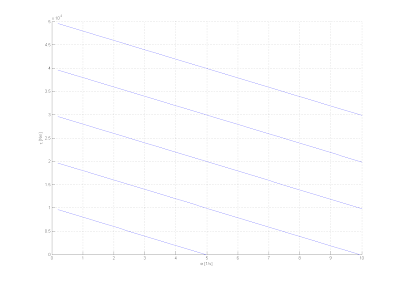
5. Draw the torque-speed curves at various voltages for your motor. You need not test at various voltages. You may draw the curves based on your motor characterization data and the motor model.
We determined our motor constant K_m by lifting various known weights and observing the thereby flowing current through the motor windings. The tau vs. current graph is shown below.We could therewith determine the motor constant as K_m=0.0153.
With this value we could draw tau - speed curves for various input voltages V_i.

6. Estimate the mechanical time constant of your motor. It will be related to your estimates of inertia and drag/damping.

The mechanical time constant of our motor remains as tau=1/delta=1.85.


7. Briefly describe what your velocity controller feels like when you turn the motor shaft. Why does it feel this way?

Position Feedback Simulation - Simulink Model:

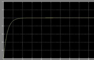
Stepresponse in Theta:


2. Certainly include the results of your experimental and theoretical frequency response experiments. Both frequency response plotted on the same graph facilitates easy visual comparison and will be duly rewarded.

We built up a theoretical simulation of our motor with voltage as input and angular displacement Theta as output. The block diagram and the transfer function is shown below.

The bode diagram remains as follows. It shows a low amplification for high frequencies as we found it in our experiments in the same way.

In a next step we measured the angular displacement of the armature as a response to different input frequencies of voltage. We plotted the maximum output amplitude over the input frequencies.
The low conformity with the theoretical data is possibly due to the fact that measuring amplitudes with the hall effect sensor resulted difficult. In each experiment it is probable to observe at least one high amplitude to other generally lower amplitudes.